Руководство по эксплуатации Siemens Synova FC330A – ManualsBase.com
Краткое содержание страницы № 1
Synova® FC330A
Fire detection system
Operating manual
System operation for user
Phase 4
Fire & Security Products
Siemens Building Technologies Group
Краткое содержание страницы № 2
Data and design subject to change without notice. / Supply subject to availability. Copyright by Siemens Building Technologies AG Wir behalten uns alle Rechte an diesem Dokument und an dem in ihm dargestellten Gegenstand vor. Der Empfänger anerkennt diese Rechte und wird dieses Dokument nicht ohne unsere vorgängige schriftliche Ermächtigung ganz oder teilweise Dritten zugänglich machen oder ausserhalb des Zweckes verwenden, zu dem es ihm übergeben worden ist.
Краткое содержание страницы № 3
Introduction . . . . . . . . . . . . . . . . . . . . . . . . . . . . . . . . . . . . . . . . . . . . . 1 About this operation manual . . . . . . . . . . . . . . . . . . . . . . . . . . . . . . . . . . . . . . . . . . . . . . . 2 Fundamentals . . . . . . . . . . . . . . . . . . . . . . . . . . . . . . . . . . . . . . . . . . . 3 Control console layout . . . . . . . . . . . . . . . . . . . . . . . . . . . . . . . . . . . . . . . . . . . . . . . . . . . . 4 Floor panel . . . . . . . . . . . . . . .
Краткое содержание страницы № 4
II 06.2003 Fire & Security Products Siemens Building Technologies Group
Краткое содержание страницы № 5
Introduction 1 Fire & Security Products e1973c-1 Siemens Building Technologies Group 02. 2004
2004
Краткое содержание страницы № 6
About this operation manual How to use this operation manual This operation manual describes the use and the operation of the control console FC330A. It contains all information for the normal user with access level 2 who has to react to alarms, disa- ble and enable parts of the system, etc. This document contains the following: Chapter Contents Page Introduction − General information about this operation ma- 1 nual − How to use this manual Fundamentals Fundamental information on the console: 3
Краткое содержание страницы № 7
Fundamentals 3 Fire & Security Products e1973c-2 Siemens Building Technologies Group 02. 2004
2004
Краткое содержание страницы № 8
Control console layout Control console FC330A ALARM NORMAL OPERATION 1 2 MON 04.01.99 09:13 Acknowledge 4 Silence/resound horn 3 5 Reset Remote alarm Alarm delay Remote alarm Start/ System on 6 78 9 F1 Stop fault / off off active Alarm horn Premises Fault F2 7 45 6 fault / off manned 8 ok Isolation System fault 12 3 Detector del 0 hm test mode 9 FC330A ALARM LED bar Red LED’s blinking when an alarm signal is pending. Text display Displays selection menus as well as alarm and fault messages
Краткое содержание страницы № 9
Floor panel The floor panel is a typical local indication terminal. It mainly serves to display alarm events re- motely. Secondary it is also an operating terminal to acknowledge and reset the control console from remote. Two types of panels are available: 1 1 ALARM zone ###/## / ###### 1( 1) ALARM zone ###/## / ###### 1( 1) 1st floor office 101 1st floor office 101 Alarm Acknowledge 3 Remote alarm Alarm actuated Reset Fault LED 1 4 System ON LED 2 2 2 5 LED 3 B3Q580 B3Q590/595 Text
Краткое содержание страницы № 10
Overview operating menu After getting operating access, the start menu appears. From the main menu, all menus can be selected (
page 9, fundamental operation). With access level 2 all menu points exept other functions − configuration can be selected. The passwort for access level 2 is: SELECT: 1. ENabling (main menu) 2. DISabling 3. INFO polling 4. other functions ENabling: 1. detector ’zone’ Enable detector zones 1. ..256 ENA
Краткое содержание страницы № 11
SELECT: 1. ENabling (main menu) 2. DISabling 3. INFO polling 4. other functions FUNCTIONS: 1. function FUNCTIONS: 1. switching alarm org. Switching manned unmanned via menu (4) 2. system TEST (4.1) 2. set time / date Set or adjust time and date 3. printout 4. configuration SYSTEM TEST: 1. horn/al.contact/RT (4.2) 2. lamps/battery page 8 3. fire and contr.zones ActivateКраткое содержание страницы № 12
SELECT: 1. ENabling (main menu) 2. DISabling 3. INFO polling 4. other functions FUNCTIONS: 1. function (4) 2. system TEST 3. printout CONFIGURATION: 1. user functions 4. configuration direct setting user parameters (4.4) 2. user text direct definition user texts 3.
Краткое содержание страницы № 13
Fundamental operation How to operate the control console To choose a menu item in the display of the console: St START system operating 1. Press . > enter password? Display shows hm /Stop: end operating ok SELECT: 1. ENabling Access level page 11 2. Enter the password and press . (main menu) 2. DISabling Display shows 3. INFO polling 4. other functions 3. Select the menu item with the and ok keys and press . or Enter the number
Краткое содержание страницы № 14
Normal operation What is “normal operation”? The system is ready to receive danger messages (alarm) from the detectors. No fault messages are pending. The green LED in the display field System on is on. The illumination of the text display may be turned off, but turns on as soon as any key is pressed or an alarm, fault or status is issued.
Краткое содержание страницы № 15
Operating access Possible access levels Three main access levels are defined allowing different privileges for the operation of the fire detection system. Access is provided by a four digit password for the higher access levels, re- spectively. After 3 consecutive incorrect password entries the operation access is disabled for 15 minu- tes. i Overview of the access levels Access level Group of persons Enabled operating functions Acknowledge messages possible: everybody − Scrolling alarm messa
Краткое содержание страницы № 16
Operating access via password The passwords are defined and released to the operators by the service engineer. del In case of misskeying the password, use to cancel keying errors. Log in START system operating St 1.
Краткое содержание страницы № 17
Operating “manned” and “unmanned” SPECIAL Alarm Concept used: Yes No i Basic rules The operating states “manned” and “unmanned” are defined in a SPECIAL Alarm Concept, where signals from automatic fire detectors and manual call points are processed differently (for details page 16). The switchover from the operating states “manned” to “unmanned” and vice versa is either done manually by the operating personnel or automatically as programmed by the service engineer. Operating
Краткое содержание страницы № 18
Toggle via menu SELECT: 1. ENabling St 1. Press . (main menu) 2. DISabling 3. INFO polling Display shows 4. other functions 2. Select option 4. 1. 1. mode ’manned’ until ##:##, 1.> unmanned sel. #, 2.> manned 3.extra time Display shows 3. If the operating state has to be changed hm: back to menu Stop: end operating to − “manned”: select option 1. − “unmanned”: select option 2. mode ’manned’ TERMINATED If mode ”manned” is selected > sys
Краткое содержание страницы № 19
Alarm 15 Fire & Security Products e1973c-3 Siemens Building Technologies Group 02.2004
Краткое содержание страницы № 20
SPECIAL Alarm Concept Purpose and principle To prevent the unnecessary turn out of the fire department for minor incidents a SPECIAL Alarm Concept was developed. It involves operating personnel in the alarming sequence and relies on two operating states: “unmanned” mode while the operating personnel is not present on the premises. “manned” mode while the operating personnel is present on the premises. “unmanned” mode When the system operates in “unmanned” mode, the fire brigade is call
инструкция Siemens FC330A
Page 1: Siemens FC330A
Synova ® FC330A Fire detection system Operating manual System operation for user Phase 4 Fire & Security Products Siemens Buildin g T echnologies Group[…]
Page 2: Siemens FC330A
Data and design subject to change without notice. / Supply subject to availability . E Copyright by Siemens Building T echnologies AG Wir behalten uns alle Rechte an diesem Dokument und an dem in ihm dargestellten Gegenstand vor .
 Der Empfänger anerkennt diese Rechte und wird dieses Dokument nicht ohne unsere vorgängige schriftliche Ermächtigung[…]
Page 3: Siemens FC330A
06.2003 I Fire & Security Pr oducts Siemens Building T echnologies Gr oup Introduction 1 . . . . . . . . . . . . . . . . . . . . . . . . . . . . . . . . . . . . . . . . . . . . . About this operation manual 2 . . . . . . . . . . . . . . . . . . . . . . . . . . . . . . . . . . . . . . . . . . . . . . . Fundamentals 3 . . . . . . . . . . . . . . […]
Page 4: Siemens FC330A
06.2003 II Fire & Security Pr oducts Siemens Building T echnologies Gr oup[…]
Page 5: Siemens FC330A
e1973c-1 02.
2004 1 Fire & Security Pr oducts Siemens Building T echnologies Gr oup Introduction[…]Page 6: Siemens FC330A
e1973c-1 02.2004 2 Fire & Security Pr oducts Siemens Building T echnologies Gr oup About this operation manual How to use this operation manual This operation manual describes the use and the operation of the control console FC330A. It contains all information for the normal user with access level 2 who has to react to alarms, disa- ble and ena[…]
Page 7: Siemens FC330A
e1973c-2 02.2004 3 Fire & Security Pr oducts Siemens Building T echnologies Gr oup Fundamentals[…]
Page 8: Siemens FC330A
e1973c-2 02.
2004 4 Fire & Security Pr oducts Siemens Building T echnologies Gr oup Control console layout Control console FC330A ALARM System on Fault Isolation Detector test mode FC330A Remote alarm fault / off Alarm horn fault / off System fault Remote alarm active Alarm delay off Premises manned hm 0 del 789 456 12 3 F1 F2 ok Start/ Stop Res[…]Page 9: Siemens FC330A
e1973c-2 02.2004 5 Fire & Security Pr oducts Siemens Building T echnologies Gr oup Floor panel The floor panel is a typical local indication terminal. It mainly serves to display alarm events re- motely . Secondary it is also an operating terminal to acknowledge and reset the control console from remote. T wo types of panels are available: B3Q5[…]
Page 10: Siemens FC330A
e1973c-2 02.
2004 6 Fire & Security Pr oducts Siemens Building T echnologies Gr oup Overview operating menu After getting operating access, the start menu appears. From the main menu, all menus can be selected ( page 9, fundamental operation). With access level 2 all menu points exept other functions − configuration can be selected. The[…]Page 11: Siemens FC330A
e1973c-2 02.2004 7 Fire & Security Pr oducts Siemens Building T echnologies Gr oup SELECT: 1. ENabling (main menu) 2. DISabling 3. INFO polling 4. other functions FUNCTIONS: 1. function (4) 2. system TEST 3. printout 4. configuration FUNCTIONS: 1. switching alarm org. (4.1) 2. set time / date Switching manned $ unmanned via menu Set or adjust t[…]
Page 12: Siemens FC330A
e1973c-2 02.
2004 8 Fire & Security Pr oducts Siemens Building T echnologies Gr oup SELECT: 1. ENabling (main menu) 2. DISabling 3. INFO polling 4. other functions FUNCTIONS: 1. function (4) 2. system TEST 3. printout 4. configuration CONFIGURATION: 1. user functions (4.4) 2. user text 3. service functions 4. erase functions direct setting user […]Page 13: Siemens FC330A
e1973c-2 02.2004 9 Fire & Security Pr oducts Siemens Building T echnologies Gr oup Fundamental operation How to operate the control console T o choose a menu item in the display of the console: 1. Press St . Display shows 2. Enter the password and press ok . Display shows 3. Select the menu item with the and keys and press ok . […]
Page 14: Siemens FC330A
e1973c-2 02.
2004 10 Fire & Security Pr oducts Siemens Building T echnologies Gr oup Normal operation What is “normal operation”? The system is ready to receive danger messages (alarm) from the detectors. No fault messages are pending. The green LED in the display field System on is on. The illumination of the text displa[…]Page 15: Siemens FC330A
e1973c-2 02.2004 11 Fire & Security Pr oducts Siemens Building T echnologies Gr oup Operating access Possible access levels Three main access levels are defined allowing different privileges for the operation of the fire detection system. Access is provided by a four digit password for the higher access levels, re- spectively . i After 3 consec[…]
Page 16: Siemens FC330A
e1973c-2 02.2004 12 Fire & Security Pr oducts Siemens Building T echnologies Gr oup Operating access via password The passwords are defined and released to the operators by the service engineer .
In case of misskeying the password, use del to cancel keying errors. Log in 1. Press St . Display shows 2. Enter the password and press ok . ?[…]Page 17: Siemens FC330A
e1973c-2 02.2004 13 Fire & Security Pr oducts Siemens Building T echnologies Gr oup Operating “manned” and “unmanned” i SPECIAL Alarm Concept used: Y es No Basic rules The operating states “manned” and “unmanned” are defined in a SPECIAL Alarm Concept, where signals from automatic fire detectors and manual call points ar[…]
Page 18: Siemens FC330A
e1973c-2 02.2004 14 Fire & Security Pr oducts Siemens Building T echnologies Gr oup T oggle via menu 1. Press St . Display shows 2. Select option 4. 1. 1. Display shows 3. If the operating state has to be changed to − “manned”: select option 1.
− “unmanned”: select option 2. If mode ”manned” is select[…]Page 19: Siemens FC330A
e1973c-3 02.2004 15 Fire & Security Pr oducts Siemens Building T echnologies Gr oup Alarm[…]
Page 20: Siemens FC330A
e1973c-3 02.2004 16 Fire & Security Pr oducts Siemens Building T echnologies Gr oup SPECIAL Alarm Concept Purpose and principle T o prevent the unnecessary turn out of the fire department for minor incidents a SPECIAL Alarm Concept was developed. It involves operating personnel in the alarming sequence and relies on two operating states: ?[…]
Page 21: Siemens FC330A
e1973c-3 02.2004 17 Fire & Security Pr oducts Siemens Building T echnologies Gr oup Alarm acknowledgement time V1 The alarm acknowledgement time is active for automatic detectors when the system opera- tes in “manned” mode.
The system checks whether someone acknowledges the alarm message within this prepro- grammed time. An alar[…]Page 22: Siemens FC330A
e1973c-3 02.2004 18 Fire & Security Pr oducts Siemens Building T echnologies Gr oup Alarm Principle An alarm is issued by the system if an automatic detector has responded or a manual call point was actuated. The alarm is indicated by: optical signals − blinking of the red LED alarm bar on the control console − alarm message on the […]
Page 23: Siemens FC330A
e1973c-3 02.2004 19 Fire & Security Pr oducts Siemens Building T echnologies Gr oup How are alarm messages shown on the text display? A single alarm message on the text display consists of 2 lines as shown in the example to the right.
The first line tells that the alarm was given in zone 5 by the element 1 of this zone, which was an automatic fi[…]Page 24: Siemens FC330A
e1973c-3 02.2004 20 Fire & Security Pr oducts Siemens Building T echnologies Gr oup[…]
Page 25: Siemens FC330A
e1973c-4 02.2004 21 Fire & Security Pr oducts Siemens Building T echnologies Gr oup Disable/Enable System Parts[…]
Page 26: Siemens FC330A
e1973c-4 02.2004 22 Fire & Security Pr oducts Siemens Building T echnologies Gr oup T emporary isolation of a detector zone What is a detector zone? The detectors and manual call points of the fire detection system are grouped into zones , which are defined according to geographical aspects of the building.
Zones may be all self-contained areas[…]Page 27: Siemens FC330A
e1973c-4 02.2004 23 Fire & Security Pr oducts Siemens Building T echnologies Gr oup Zone isolation procedure 1. Press St . Display shows 2. Select option 2. 1. 1. Display shows Now you can disable single zones, a range of detector zones or all zones as described be- low: Disable single zones 1. Enter the desired zone num[…]
Page 28: Siemens FC330A
e1973c-4 02.2004 24 Fire & Security Pr oducts Siemens Building T echnologies Gr oup Disable all zones 1. Enter 555 to disable all zones in the building. Display shows 2. Enter 99 for permanent disabling. Display shows or ” Enter the desired disabling time in full hours (e. g. 2). Display shows 3.
Press St to finish […]Page 29: Siemens FC330A
e1973c-4 02.2004 25 Fire & Security Pr oducts Siemens Building T echnologies Gr oup Enable single zones 1. Enter the number of a zone to be ena- bled (e. g. 2). Display shows With a running timeout after which the zone is automatically enabled. 2. Enter another zone number to enable or press F1 to enable the zone before the timeout […]
Page 30: Siemens FC330A
e1973c-4 02.2004 26 Fire & Security Pr oducts Siemens Building T echnologies Gr oup T emporary isolation of a single detector When has a single detector to be isolated? Exceptional situations may occur , where it is preferable to isolate only single detector devices instead of the whole detector zone. Such situations may be for example: Con[.
..]Page 31: Siemens FC330A
e1973c-4 02.2004 27 Fire & Security Pr oducts Siemens Building T echnologies Gr oup Detector reactivation procedure 1. Press St . Display shows 2. Select option 1. 1. 2. Display shows 3. Enter the desired zone number . Display shows 4. Enter the desired element number . Display shows 5. Enter another elem[…]
Page 32: Siemens FC330A
e1973c-5 02.2004 28 Fire & Security Pr oducts Siemens Building T echnologies Gr oup Remote T ransmission i Remote transmission provided: No Y es Alarm to: Fault transmission provided: No Y es Alarm to: What is “remote transmission”? The remote transmission facility establishes a transmission path to the fire department in th[…]
Page 33: Siemens FC330A
e1973c-5 02.
2004 29 Fire & Security Pr oducts Siemens Building T echnologies Gr oup Disabling the remote fault transmission facility 1. Press St . Display shows 2. Select option 2. 2. 4. Display shows for a few seconds The remote fault transmission is disabled. The yellow LED of the display field Isolation is on.[…]Page 34: Siemens FC330A
e1973c-6 02.2004 30 Fire & Security Pr oducts Siemens Building T echnologies Gr oup Alarm devices When have alarm devices to be disabled? Under normal conditions the alarm devices (e. g. horns or sirens) operate in active stand − by . They are only disabled for: T est of the fire detection system. Maintenance and conversion works on t[…]
Page 35: Siemens FC330A
e1973c-7 02.2004 31 Fire & Security Pr oducts Siemens Building T echnologies Gr oup Faults[.
..]Page 36: Siemens FC330A
e1973c-7 02.2004 32 Fire & Security Pr oducts Siemens Building T echnologies Gr oup Faults How do I respond to fault messages? Fault messages are issued on the text display if a malfunction in the system, the cabling or the attached devices is detected. Additionally the LED in the fault display field is blinking. 1. Confirm the message by press[…]
Page 37: Siemens FC330A
e1973c-8 02.2004 33 Fire & Security Pr oducts Siemens Building T echnologies Gr oup Maintenance[…]
Page 38: Siemens FC330A
e1973c-8 02.2004 34 Fire & Security Pr oducts Siemens Building T echnologies Gr oup Detector test Purpose and Principle For function tests of the automatic fire detectors and the manual call points, zones of the fire detection system are set into the “detector test mode”.
In the detector test mode a responding detector or manual call point […]Page 39: Siemens FC330A
e1973c-8 02.2004 35 Fire & Security Pr oducts Siemens Building T echnologies Gr oup 4. After entering the last number press ok twice. Display shows for a few seconds The selected detector zones are set into detector test mode. Display shows The yellow LED of the display field de- tector test mode are on. Setting a zone r[…]
Page 40: Siemens FC330A
e1973c-8 02.2004 36 Fire & Security Pr oducts Siemens Building T echnologies Gr oup Functional testing of automatic AlgoRex-detectors Required equipement There are basically two kinds of automatic fire detectors: heat detectors and smoke detectors. For heat detectors the detector tester RE6T is required, which simulates the temperatur rise with[.
..]Page 41: Siemens FC330A
e1973c-8 02.2004 37 Fire & Security Pr oducts Siemens Building T echnologies Gr oup Functional test of manual call points T est procedure for type KAC 1. Set the desired zone into detector test mode ( page 34). 2. Insert the test key into the opening at the lower left side of the housing. A test alarm is simulated. 3. Observe, whethe[…]
Page 42: Siemens FC330A
e1973c-9 02.2004 38 Fire & Security Pr oducts Siemens Building T echnologies Gr oup Lamp test Purpose of the lamp test Alarms, faults and operating state of the fire detection system are indicated by LEDs in the dis- play fields, the text display and the alarm buzzer of the control console. T o check the correct function of these parts the lamp[.
..]Page 43: Siemens FC330A
e1973c-10 02.2004 39 Fire & Security Pr oducts Siemens Building T echnologies Gr oup Battery load test Purpose and principle In case of mains interruption the power supply of the fire detection system relies on an internal battery pack. The capacity of the battery pack is sufficent to keep the system for a couple of hours operating ( pag[…]
Page 44: Siemens FC330A
e1973c-11 02.2004 40 Fire & Security Pr oducts Siemens Building T echnologies Gr oup T est of acoustic alarm devices Purpose and principle The fire detection system is equipped with acoustic alarm devices distributed throughout the building t o alarm the fire brigade in case of fire. The function of the acoustic alarm devices has to be checked [.
..]Page 45: Siemens FC330A
e1973c-12 02.2004 41 Fire & Security Pr oducts Siemens Building T echnologies Gr oup T est of Remote T ransmission (RT) Purpose and principle In test mode the function of the remote transmission can be tested without activating an alarm device or a manual call point. Th e function of the remote transmission facility has to be checked periodical[…]
Page 46: Siemens FC330A
e1973c-12 02.2004 42 Fire & Security Pr oducts Siemens Building T echnologies Gr oup[…]
Page 47: Siemens FC330A
e1973c-13 02.2004 43 Fire & Security Pr oducts Siemens Building T echnologies Gr oup Other Functions[.
..]Page 48: Siemens FC330A
e1973c-13 02.2004 44 Fire & Security Pr oducts Siemens Building T echnologies Gr oup Printer disabling/enabling i Printer connected: Y es No When has the printer to be disabled? Under normal conditions the printer operates in active stand-by . It is only disabled in special ca- ses e. g. for change of paper or repair . Disabling the pri[…]
Page 49: Siemens FC330A
e1973c-13 02.2004 45 Fire & Security Pr oducts Siemens Building T echnologies Gr oup Paper replacement with logging printer B2Q191 Switch off the printer Before changing the printer paper disable the printer by the control panel menu ( page 44). B C E D A F G H J I II III IV B2Q101 V Change of printer paper 1. Remove the screws on the ri[.
..]Page 50: Siemens FC330A
e1973c-14 02.2004 46 Fire & Security Pr oducts Siemens Building T echnologies Gr oup Poll alarm counter Purpose of polling the alarm counter The alarm counter allows to get information about the number of alarms and remote alarms in the past. Polling the alarm counter 1. Press St . Display shows 2. Select option 3. 2. 2. Dis[…]
Page 51: Siemens FC330A
e1973c-14 02.2004 47 Fire & Security Pr oducts Siemens Building T echnologies Gr oup Poll event memory Purpose of polling the event memory Th e event memory allows to get information about events registered by the fire detection system in the past. Always the last 200 events are registered by the system. Polling the event memory 1. Press St . ?[.
..]Page 52: Siemens FC330A
e1973c-14 02.2004 48 Fire & Security Pr oducts Siemens Building T echnologies Gr oup Poll user text of zones or elements Purpose The assignment of the zone numbers to the descriptive user text is stored in the memory of the fire detection system and can be displayed on the text display of the control console. Polling user text of zones or eleme[…]
Page 53: Siemens FC330A
e1973c-14 02.2004 49 Fire & Security Pr oducts Siemens Building T echnologies Gr oup Poll system status Purpose After acknowledging messages from various system states dif fering from “normal operation” as “isolation” or “fault”, detailed information may be no longer visible on the text display . Only the LEDs of the display fields [.
..]Page 54: Siemens FC330A
e1973c-14 02.2004 50 Fire & Security Pr oducts Siemens Building T echnologies Gr oup Poll configuration data Purpose The polling of configuration data is only relevant for the service engineer , for controlling user functions without the configuration tool. Polling configuration data of detector zones 1. Press St . Display shows 2. Sele[…]
Page 55: Siemens FC330A
e1973c-15 02.2004 51 Fire & Security Pr oducts Siemens Building T echnologies Gr oup Printout All informations that can be polled also can be printed, if a printer is connected. Print system status 1. Press St . Display shows 2. Select option 4. 3. 1. Display shows 3. Select the information to be printed. Display sho[…]
Page 56: Siemens FC330A
e1973c-16 02.
2004 52 Fire & Security Pr oducts Siemens Building T echnologies Gr oup Set time and date i Changeover summertime to wintertime: manually automatically Purpuse and Principle Time and date are set by the service engineer when the system is put into service. Under normal conditions there is no need to correct time and date. T[…]Page 57: Siemens FC330A
Back 02.2004 53 Fire & Security Pr oducts Siemens Building T echnologies Gr oup[…]
Page 58: Siemens FC330A
Back 02.2004 54 Fire & Security Pr oducts Siemens Building T echnologies Gr oup Document no. Edition e1973c 02.2004 Siemens Building T echnologies AG CH-8708 Männedorf Alte Landstrasse 411 T el. Fax www .cerberus.ch +41 1 − 922 61 11 +41 1 − 922 64 50 Manual FD-M Section 8[.
..]
 Der Empfänger anerkennt diese Rechte und wird dieses Dokument nicht ohne unsere vorgängige schriftliche Ermächtigung[…]
 2004 1 Fire & Security Pr oducts Siemens Building T echnologies Gr oup Introduction[…]
 2004 4 Fire & Security Pr oducts Siemens Building T echnologies Gr oup Control console layout Control console FC330A ALARM System on Fault Isolation Detector test mode FC330A Remote alarm fault / off Alarm horn fault / off System fault Remote alarm active Alarm delay off Premises manned hm 0 del 789 456 12 3 F1 F2 ok Start/ Stop Res[…]
 2004 6 Fire & Security Pr oducts Siemens Building T echnologies Gr oup Overview operating menu After getting operating access, the start menu appears. From the main menu, all menus can be selected ( page 9, fundamental operation). With access level 2 all menu points exept other functions − configuration can be selected. The[…]
 2004 8 Fire & Security Pr oducts Siemens Building T echnologies Gr oup SELECT: 1. ENabling (main menu) 2. DISabling 3. INFO polling 4. other functions FUNCTIONS: 1. function (4) 2. system TEST 3. printout 4. configuration CONFIGURATION: 1. user functions (4.4) 2. user text 3. service functions 4. erase functions direct setting user […]
 2004 10 Fire & Security Pr oducts Siemens Building T echnologies Gr oup Normal operation What is “normal operation”? The system is ready to receive danger messages (alarm) from the detectors. No fault messages are pending. The green LED in the display field System on is on. The illumination of the text displa[…]
 In case of misskeying the password, use del to cancel keying errors. Log in 1. Press St . Display shows 2. Enter the password and press ok . ?[…]
 − “unmanned”: select option 2. If mode ”manned” is select[…]
 The system checks whether someone acknowledges the alarm message within this prepro- grammed time. An alar[…]
 The first line tells that the alarm was given in zone 5 by the element 1 of this zone, which was an automatic fi[…]
The first line tells that the alarm was given in zone 5 by the element 1 of this zone, which was an automatic fi[…] Zones may be all self-contained areas[…]
 Press St to finish […]
 ..]
..] 2004 29 Fire & Security Pr oducts Siemens Building T echnologies Gr oup Disabling the remote fault transmission facility 1. Press St . Display shows 2. Select option 2. 2. 4. Display shows for a few seconds The remote fault transmission is disabled. The yellow LED of the display field Isolation is on.[…]
 ..]
..] In the detector test mode a responding detector or manual call point […]
 ..]
..] ..]
..] ..]
..] ..]
..] ..]
..] ..]
..] ..]
..] 2004 52 Fire & Security Pr oducts Siemens Building T echnologies Gr oup Set time and date i Changeover summertime to wintertime: manually automatically Purpuse and Principle Time and date are set by the service engineer when the system is put into service. Under normal conditions there is no need to correct time and date. T[…]
 ..]
..]SIEMENS SYNOVA FC330A РУКОВОДСТВО Скачать Pdf
Содержание
3страница из 136
- Содержание
- Оглавление
- Поиск неисправностей
- Закладки
Реклама
СОДЕРЖАНИЕ
СОДЕРЖАНИЕ
1 ПЛАНИРОВАНИЕ
Доступные базовые контрольные единицы
СВОДЕСТВЕННЫЕ ДАННЫХ FC330A-x (4 2003
.
(4 петли)Accessories as Supplied with FC330A-ECO
Ordering Information FC330A Cabinet Series ‘Standard
Ordering Information FC330A in Special Cabinet
Language Kits
Ordering Information for Floor Repeater and Control Panels
Запасные части (4 петли)
2 Установка
Монтажный шкаф
Защита установленного шкафа
монтаж набора удлинения аккумулятора Z3I1020 до FC330A-X (4 петли)
монтаж опциональных карт FC330A-ECO (1 Loop)
- 666. ECO-CH (1 шлейф)
Установка дополнительных плат FC330A-X (4 шлейфа)
Установка дополнительных плат FC330A-2-CH (4 шлейфа)
Возможные комбинации 9003
0025
монтаж дополнительной панели параллельного индикатора B3R080 или на крышке H33B030
монтаж дополнительного переключателя ключей Z3S020 ‘Nordic’ или Z3S030 ‘KABA
Mounting of Apply Fiels Fulls Supply-x.
c330110Mounting of Apply Fiels Supply Supply-x. 100003
Обзор операционного меню
 (4 петли)
 c330110
5 Настройки приложения пользователя
Основные средства
Пользовательские функции
У пользовательского приложения.
Обзор меню SWE330A
Блок управления передачей данных <−> SWE330A
Настройки приложения пользователя «Напрямую» с клавиатуры
Define General Functions
Define Parameters on Zone
6 Background Information
Power Supply
Programmable Alarm Organization
Synoloop
Control Line for Alarm Устройства (звуковой сигнал)
Контакты управления
Выходы удаленной передачи (RT)
Последовательные порты
Serial Port Application VISU (Visualizer)
7 Trouble Shooting
Interpretation of Fault Messages
8 Maintenance
General
Recommended System Performance Checks
9 Приложение
Synova) Список полевых устройств FC330A −> Synoloop
Synova) Процедура быстрого ввода в эксплуатацию FC330A
Synova) Самодельные полосы для надписей
Synova® FC330A
Система обнаружения пожаров
Планирование
Установка
Пополнение
Системная работа
Настройки приложения пользователя
Фоновая информация
Устранение неполадок
. 0002 Фаза 4
Строительные технологии
Противопожарная безопасность
Содержание
Предыдущая страница
Следующая страница
Содержание
Краткое содержание для Siemens Synova FC330A
Siemens Synova FC330A инструкция по эксплуатации – ManualsBase.com
Краткое содержание страницы № 1
Synova® FC330A
Система обнаружения пожара
Руководство по эксплуатации
Работа системы для пользователя
Фаза 4
Продукты для пожарной безопасности и безопасности
Siemens Building Technologies Group
Краткое содержание страницы № 2
Данные и дизайн могут быть изменены без предварительного уведомления. / Поставка при наличии. Авторское право принадлежит Siemens Building Technologies AG. Мы предоставляем все права на документ и дем в их dargestellten Gegenstand vor. Der Empfänger anerkennt diese Rechte und wird dieses Dokument nicht ohne unsere vorgängige schriftliche Ermächtigung ganz oder teilweise Dritten zugänglich machen oder ausserhalb des Zweckes verwenden, zu dem es ihm übergeben worden ist. Мы оставляем за собой все права на этот документ
Краткое содержание страницы № 3
Введение . . . . . . . . . . . . . . . . . . . . . . . . . . . . . . . . . . . . . . . . . . . . . 1 Об этом руководстве по эксплуатации. . . . . . . . . . . . . . . . . . . . . . . . . . . . . . . . . . . . . . . . . . . . . . . 2 Основы. . . . . . . . . . . . . . . . . . . . . . . . . . . . . . . . . . . . . . . . . . . 3 Компоновка консоли управления. . . . . . . . . . . . . . . . . . . . . . . . . . . . . . . . . . . . . . . . . . . . . . . . . . . . 4 Панель пола. . . . . . . . . . . . . . .
Краткое содержание страницы № 4
II 06.2003 Продукция пожарной безопасности Siemens Building Technologies Group
Краткое содержание страницы № 5
Введение 1 Продукты пожарной безопасности e1973c-1 Siemens Building Technologies Group 02. 2004
2004
Краткое содержание страницы № 6
О данном руководстве по эксплуатации Как пользоваться данным руководством по эксплуатации В данном руководстве по эксплуатации описывается использование и работа пульта управления FC330A. Он содержит всю информацию для обычного пользователя с уровнем доступа 2, который должен реагировать на сигналы тревоги, отключать и включать части системы и т. д. Этот документ содержит следующее: Глава Содержание Страница Введение − Общая информация об этой операции 1 nual — Как пользоваться этим руководством Основы Основная информация о консоли: 3
Краткое содержание страницы № 7
Основы 3 Продукты пожарной безопасности и безопасности e1973c-2 Siemens Building Technologies Group 02.2004
Краткое содержание страницы № 8
Схема пульта управления Пульт управления FC330A ТРЕВОГА НОРМАЛЬНАЯ РАБОТА 1 2 ПН 01.04.99 09:13 Подтверждение 4 Тишина/звук сирены 3 5 Сброс Удаленная тревога Задержка тревоги Удаленная тревога Пуск/Система вкл. 6 78 9 F1 Стоп Ошибка / выкл. Неисправность F2 7 45 6 неисправность / не работает 8 в норме Изоляция Неисправность системы 12 3 Детектор дел 0 hm тестовый режим 9 FC330A Светодиодная полоса ALARM Красный светодиод мигает, когда ожидается сигнал тревоги. Текстовый дисплей Отображает меню выбора, а также аварийные сообщения и сообщения об ошибках
Краткое содержание страницы № 9
Напольная панель Напольная панель представляет собой типичный местный терминал индикации. В основном он служит для удаленного отображения тревожных событий. Во-вторых, это также операционный терминал для подтверждения и сброса консоли управления с пульта. Доступны два типа панелей: 1 1 Зона ТРЕВОГИ ###/## / ###### 1( 1) Зона ТРЕВОГИ ###/## / ###### 1( 1) Офис 1-го этажа 101 Офис на 1-м этаже 101 Подтверждение тревоги 3 Удаленная тревога Сработала тревога Сброс Сбой Светодиод 1 4 Система включена Светодиод 2 2 2 5 Светодиод 3 B3Q580 B3Q590/595 Текст
Краткое содержание страницы № 10
Обзор рабочего меню После получения доступа к управлению появляется начальное меню. В главном меню можно выбрать все меню (
стр. 9, основные операции). С уровнем доступа 2 можно выбрать все пункты меню, кроме других функций − конфигурации. Пароль для уровня доступа 2: ВЫБОР: 1. ВКЛЮЧЕНИЕ (главное меню) 2. ОТКЛЮЧЕНИЕ 3. Опрос INFO 4. Другие функции Включение: 1. «зона извещателя» Включение зон извещателя 1…256 ENA
В главном меню можно выбрать все меню (
стр. 9, основные операции). С уровнем доступа 2 можно выбрать все пункты меню, кроме других функций − конфигурации. Пароль для уровня доступа 2: ВЫБОР: 1. ВКЛЮЧЕНИЕ (главное меню) 2. ОТКЛЮЧЕНИЕ 3. Опрос INFO 4. Другие функции Включение: 1. «зона извещателя» Включение зон извещателя 1…256 ENA
Краткое содержание страницы № 11
ВЫБОР: 1. ВКЛЮЧЕНИЕ (главное меню) 2. ОТКЛЮЧЕНИЕ 3. Опрос ИНФО 4. другие функции ФУНКЦИИ: 1. функция ФУНКЦИИ: 1. переключение сигнализации орг. Переключение с рабочего на беспилотный через меню (4) 2. ТЕСТ системы (4.1) 2. установка времени/даты Установка или настройка времени и даты 3. распечатка 4. конфигурация ТЕСТ СИСТЕМЫ: 1. сирена/ал.контакт/RT (4.2) 2. лампы/аккумулятор стр. 8 3. пожарная и контр.зоны Активировать
Краткое содержание страницы № 12
ВЫБОР: 1. ВКЛЮЧЕНИЕ (главное меню) 2. ОТКЛЮЧЕНИЕ 3. Опрос ИНФОРМАЦИИ 4. другие функции ФУНКЦИИ: 1. функция (4) 2. ТЕСТ системы 3. распечатка КОНФИГУРАЦИЯ: 1. функции пользователя 4. настройка параметров пользователя (4.4) ) 2. пользовательский текст прямое определение пользовательских текстов 3. сервисные функции 4. функции стирания Уровень СЕРВИСНЫЕ ФУНКЦИИ > ввести пароль? хм: вернуться в меню
Краткое содержание страницы № 13
Основные операции Как работать с консолью управления Чтобы выбрать пункт меню на дисплее консоли: St ЗАПУСК работы системы 1. Нажмите . > ввести пароль? На дисплее отображается hm /Stop: конец работы ok ВЫБОР: 1. Активация уровня доступа стр. 11 2. Введите пароль и нажмите . (главное меню) 2. ОТКЛЮЧЕНИЕ На дисплее отображается 3. Опрос ИНФОРМАЦИИ 4. другие функции 3. Выберите пункт меню с помощью кнопок и ok и нажмите . или Введите номер
Краткое содержание страницы № 14
Нормальная работа Что такое «нормальная работа»? Система готова к приему сообщений об опасности (тревоги) от извещателей. Сообщений об ошибках не ожидается. Зеленый светодиод в поле дисплея Горит система. Подсветка текстового дисплея может быть выключена, но включается при нажатии любой клавиши или при появлении аварийного сигнала, неисправности или статуса. НОРМАЛЬНАЯ РАБОТА На дисплее отображается СРЕДА 21.7.99 15:00 Прерывание сети В случае прерывания сети система пожарной сигнализации получает питание от
Краткое содержание страницы № 15
Рабочий доступ Возможные уровни доступа Определены три основных уровня доступа, обеспечивающие различные привилегии для работы с системой обнаружения пожара. Доступ обеспечивается четырехзначным паролем для более высоких уровней доступа соответственно. После 3-х последовательных неверных вводов пароля доступ к операции отключается на 15 минут. i Обзор уровней доступа Уровень доступа Группа лиц Включенные рабочие функции Возможно подтверждение сообщений: все − Прокрутка тревожного сообщения
Краткое содержание страницы № 16
Доступ к работе через пароль Пароли определяются и сообщаются операторам сервисным инженером.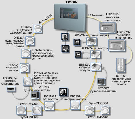 del В случае неправильного ввода пароля используйте для отмены ошибок ввода. Войти в систему START, работающую St 1. Нажмите . > ввести пароль? На дисплее отображается hm /Stop: конец работы ok 2. Введите пароль и нажмите . ВЫБОР: 1. ВКЛЮЧЕНИЕ (главное меню) 2. ОТКЛЮЧЕНИЕ На дисплее отображается 3. Опрос INFO 4. Другие функции 3. Продолжение работы (согл.
Краткое содержание страницы № 17
Использование СПЕЦИАЛЬНОЙ концепции сигнализации в режимах «обслуживание» и «без присутствия человека»: Да Нет i Основные правила Рабочие состояния «обслуживание» и «без присутствия человека» определяются в концепции СПЕЦИАЛЬНОЙ тревоги, в которой сигналы от автоматических пожарных извещателей и ручных извещателей обрабатываются по-разному ( подробности стр. 16). Переключение из рабочего состояния «обслуживаемый» в «автоматический» и наоборот осуществляется либо вручную обслуживающим персоналом, либо автоматически по программе сервисного инженера. Операционная
Краткое содержание страницы № 18
Переключение через меню SELECT: 1. Включение St 1. Нажмите . (главное меню) 2. ОТКЛЮЧЕНИЕ 3. Опрос ИНФО На дисплее отображается 4. другие функции 2. Выберите опцию 4. 1. 1. режим «обслуживаемый» до ##:##, 1.> выбор беспилотного режима. #, 2.> обслуживаемый 3.дополнительное время На дисплее отображается 3. Если необходимо изменить рабочее состояние hm: вернуться в меню Stop: завершить работу на − «обслуживаемый»: выбрать вариант 1. − «необслуживаемый»: выбрать вариант 2. режим ‘обслуживаемый’ TERMINATED Если выбран режим ‘обслуживаемый’ > sys
Краткое содержание страницы № 19
Alarm 15 Fire & Security Products e1973c-3 Siemens Building Technologies Group 02.2004
Краткое содержание страницы № 20
Концепция СПЕЦИАЛЬНОЙ сигнализации Цель и принцип Для предотвращения ненужного выезда пожарной части при незначительных происшествиях была разработана Концепция СПЕЦИАЛЬНОЙ сигнализации. Он вовлекает обслуживающий персонал в тревожную последовательность и опирается на два режима работы: «беспилотный» режим, когда обслуживающий персонал отсутствует на территории.